No single vacuum pump covers the whole range from atmosphere to ultra-high vacuum. This guide compares every major
pump type by working principle, ultimate pressure, pumping speed and best-fit application.
Values are typical ranges across manufacturers; check the data sheet for a specific model.
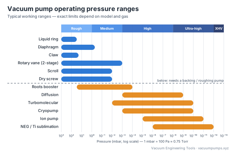
Vacuum pump operating pressure ranges.
Typical operating ranges of vacuum pump types. Pumps below the dashed line need a backing or roughing pump.
Use this diagram
Free to use in articles, training material and presentations — please link back to this page.
Positive displacement pumps
Rotary vane (oil-sealed)
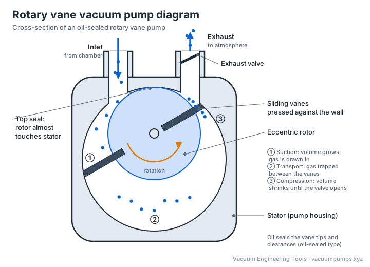
An eccentric rotor with sliding vanes traps gas and compresses it toward the exhaust; oil seals and lubricates the gaps.
Rotary vane vacuum pump diagram.
Rotary vane pump: an eccentric rotor with sliding vanes draws gas in through the inlet, traps it, and compresses it until the exhaust valve opens.
Use this diagram
Free to use in articles, training material and presentations — please link back to this page.
Ultimate pressure
≈10⁻¹ mbar (1-stage), ≈10⁻³ mbar (2-stage)
Pumping speed
1 – 1,600 m³/h
Advantages
Low cost per m³/h, robust, good ultimate pressure, huge installed base
Limitations
Oil maintenance, risk of oil backstreaming, condensable vapours contaminate oil (use gas ballast)
Limited ultimate pressure and speed, diaphragm and valve wear
Typical uses
Rotary evaporation, filtration, gel dryers, backing small turbo pumps
Scroll
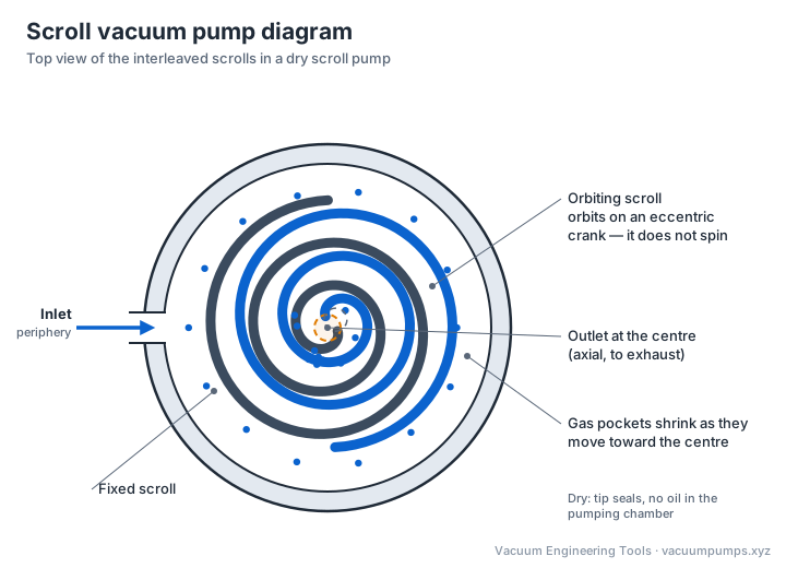
Two interleaved spirals, one orbiting, trap pockets of gas and move them toward the centre while compressing them.
Scroll vacuum pump diagram.
Scroll pump: the orbiting scroll traps gas at the periphery and pushes the shrinking pockets toward the centre, where the compressed gas exits.
Use this diagram
Free to use in articles, training material and presentations — please link back to this page.
Ultimate pressure
≈10⁻² mbar
Pumping speed
5 – 60 m³/h
Advantages
Clean, dry, quiet, good ultimate pressure for a dry pump
Limitations
Tip-seal replacement, sensitive to particles, moderate speed range
Typical uses
Electron microscopes, analytical instruments, backing turbo pumps, clean labs
Dry screw
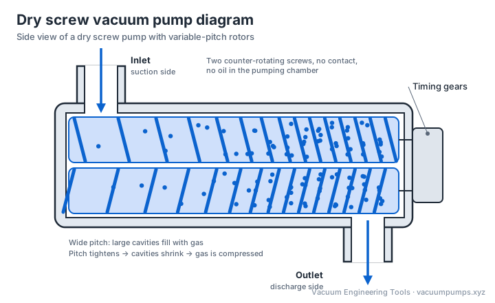
Two intermeshing helical rotors turn without contact, moving gas axially from inlet to exhaust.
Dry screw vacuum pump diagram.
Dry screw pump: two counter-rotating screws move gas axially; a tighter pitch toward the discharge end compresses it without any oil in the pumping chamber.
Use this diagram
Free to use in articles, training material and presentations — please link back to this page.
Ultimate pressure
≈10⁻² mbar
Pumping speed
100 – 2,500+ m³/h
Advantages
Oil-free, handles vapours and some particles, low maintenance, high speed
Chemical & pharma processing, semiconductor load locks, industrial drying, coating
Claw
Two claw-shaped rotors rotate in opposite directions without contact, trapping and compressing gas.
Ultimate pressure
≈20 – 150 mbar (single-stage)
Pumping speed
50 – 1,000 m³/h
Advantages
Oil-free, very energy efficient in rough vacuum, low maintenance
Limitations
Limited ultimate pressure
Typical uses
Pneumatic conveying, woodworking hold-down, CNC tables, central hospital vacuum, milking
Roots (booster)
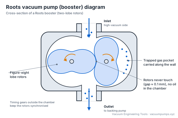
Two figure-eight lobes rotate in sync without contact; boosts the speed of a backing pump in the 1–10⁻³ mbar range.
Roots vacuum pump (booster) diagram.
Roots booster: two lobed rotors turn in opposite directions without touching, carrying pockets of gas from the inlet around the housing wall to the outlet.
Use this diagram
Free to use in articles, training material and presentations — please link back to this page.
Ultimate pressure
≈10⁻⁴ mbar (with backing pump)
Pumping speed
100 – 10,000+ m³/h
Advantages
Multiplies pumping speed 5–10× at medium vacuum, compact, efficient
Limitations
Needs a backing pump, limited compression ratio, overheats at high inlet pressure without bypass
Typical uses
Vacuum furnaces, coating, freeze drying, large rough/medium vacuum systems
Liquid ring
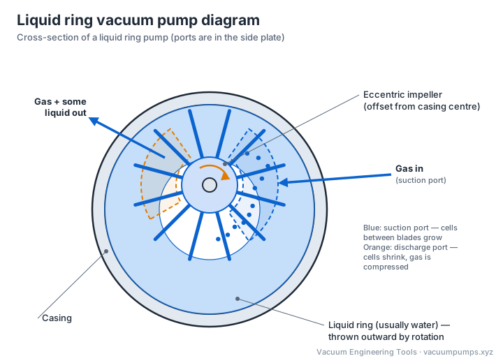
An eccentric impeller spins a ring of sealing liquid; spaces between the blades and the ring expand and contract.
Liquid ring vacuum pump diagram.
Liquid ring pump: the eccentric impeller spins a ring of liquid; the cells between the blades grow over the suction port and shrink over the discharge port.
Use this diagram
Free to use in articles, training material and presentations — please link back to this page.
Ultimate pressure
≈25 – 33 mbar (limited by liquid vapour pressure)
Pumping speed
25 – 30,000 m³/h
Advantages
Tolerates liquid carry-over, vapours and dirt, isothermal compression, very robust
Limitations
High energy and water use, ultimate pressure set by seal-liquid temperature
Typical uses
Paper machines, power plant condensers, chemical processing, sterilisers
Kinetic / momentum transfer pumps
Steam / gas ejector
A high-velocity motive jet (steam, air or liquid) entrains gas through a venturi.
Ultimate pressure
≈0.1 mbar (multi-stage steam)
Pumping speed
Up to very large capacities
Advantages
No moving parts, handles corrosive and dirty gas, cheap to build
Limitations
High motive-fluid consumption, low efficiency
Typical uses
Refinery vacuum distillation, evaporators, deodorisers, lab water aspirators
Turbomolecular
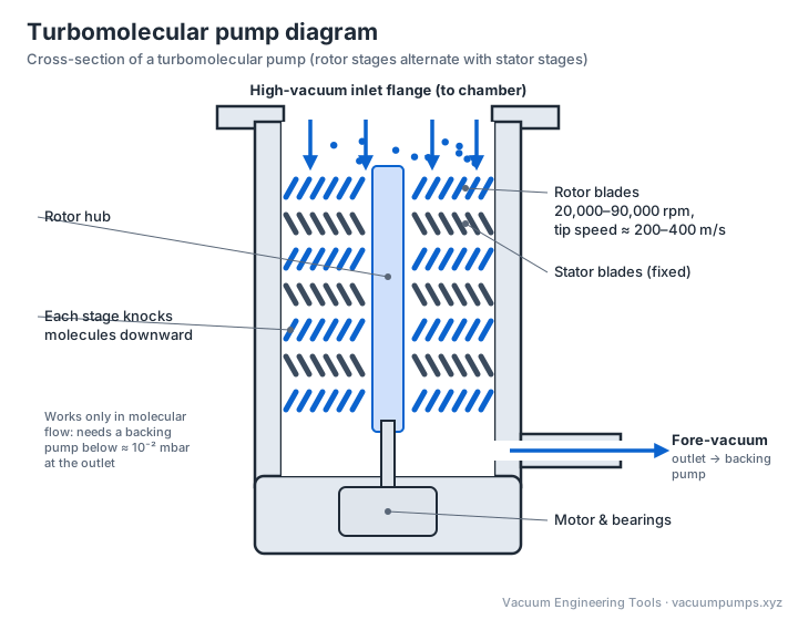
Rotor blades spinning at 20,000–90,000 rpm give gas molecules a momentum toward the exhaust; works only in molecular flow.
Turbomolecular pump diagram.
Turbomolecular pump: fast-spinning rotor blades knock gas molecules downward stage by stage; a backing pump removes them from the fore-vacuum outlet.
Use this diagram
Free to use in articles, training material and presentations — please link back to this page.
Ultimate pressure
≈10⁻⁹ – 10⁻¹⁰ mbar
Pumping speed
10 – 4,000 L/s
Advantages
Clean, fast start-up, wide range, no cryogens
Limitations
Needs a backing pump (≈10⁻² mbar), sensitive to shock and particles, lower speed for H₂/He
Typical uses
Mass spectrometry, SEM/TEM, thin-film deposition, research, leak detectors
Oil diffusion
Heated oil vapour jets directed downward knock gas molecules toward the backing pump.
Ultimate pressure
≈10⁻⁹ mbar (with cold trap)
Pumping speed
50 – 50,000 L/s
Advantages
No moving parts, very high speed per cost, reliable
Limitations
Oil backstreaming risk, long heat-up/cool-down, needs baffles and cold traps
Typical uses
Large vacuum furnaces, coating plants, space simulation chambers
Entrapment (capture) pumps
Cryopump
Surfaces cooled to 10–20 K condense and adsorb gases; charcoal adsorbs H₂, He and Ne.
Ultimate pressure
≈10⁻¹⁰ mbar
Pumping speed
1,000 – 60,000 L/s
Advantages
Very high speed for water vapour, clean, no backing during operation
Limitations
Needs periodic regeneration, limited capacity, compressor & cold head maintenance
Typical uses
Semiconductor sputtering and implantation, space simulation, large coaters
Sputter-ion pump
A Penning discharge ionises gas; ions are buried in titanium cathodes that also chemically getter active gases.
Ultimate pressure
≈10⁻¹¹ mbar
Pumping speed
1 – 1,000 L/s
Advantages
No moving parts, vibration-free, bakeable, runs for years, doubles as a pressure gauge
Limitations
Must be started below ~10⁻⁵ mbar, low speed for noble gases, heavy magnets
Typical uses
UHV surface science, particle accelerators, electron microscope guns
NEG / titanium sublimation
Reactive metal surfaces chemically bind active gases (H₂, CO, N₂, O₂, H₂O).
Ultimate pressure
≈10⁻¹² mbar
Pumping speed
High for H₂ and active gases
Advantages
Compact, no power during pumping (NEG), excellent for H₂ in UHV/XHV
Limitations
Do not pump noble gases or methane, need activation, finite capacity
Typical uses
Accelerators, XHV systems, sealed devices, supplementing ion pumps
Vacuum pump selection guide
Application
Typical pump choice
HVAC/R system evacuation (to 500 microns)
Two-stage rotary vane (portable)
Rotary evaporator / lab solvent work
Chemistry-resistant diaphragm (PTFE)
Freeze drying
Two-stage rotary vane or scroll (+ Roots for large units)
Vacuum packaging (food)
Single-stage oil-sealed rotary vane
CNC hold-down / vacuum tables
Claw or rotary vane (dry or oil)
Chemical / pharma process
Dry screw, or liquid ring for wet/dirty service
Electron microscope / mass spec
Scroll or rotary vane backing + turbomolecular
Thin-film coating (PVD)
Dry screw/Roots roughing + cryopump or turbo
Surface science (UHV)
Turbo + ion pump + titanium sublimation / NEG, with bake-out
Vacuum pumps fall into three groups. Positive displacement pumps (rotary vane, diaphragm, scroll, screw, claw, Roots, liquid ring) trap and expel gas mechanically and work from atmosphere down to medium vacuum. Kinetic pumps (turbomolecular, diffusion, ejectors) transfer momentum to gas molecules. Entrapment pumps (cryopumps, ion pumps, getters) capture gas on surfaces and reach ultra-high vacuum.
What is the difference between a single-stage and a two-stage vacuum pump?
A two-stage pump has two pumping mechanisms in series: the first stage exhausts into the second instead of directly to atmosphere. This reduces the back-leakage at the inlet, so a two-stage rotary vane pump reaches around 10⁻³ mbar versus about 10⁻¹ mbar for a single-stage pump.
What is the difference between wet and dry vacuum pumps?
Wet (oil-sealed or liquid ring) pumps use a fluid in the pumping chamber to seal, lubricate and cool. Dry pumps (scroll, screw, claw, diaphragm, Roots, turbo) have no fluid in the gas path, so they cannot contaminate the process with oil and need less fluid maintenance, but usually cost more.
Why does a turbomolecular pump need a backing pump?
Turbo pumps only work in molecular flow and have a limited compression ratio, so their exhaust must be held at roughly 10⁻² to 10 mbar by a backing (fore-vacuum) pump such as a scroll, diaphragm or rotary vane pump. They cannot exhaust directly to atmosphere.
How do I choose a vacuum pump?
Start from the pressure you need and the gas load: pick a pump type whose ultimate pressure is at least one decade below your working pressure, then size the speed with the pump-down and gas-load requirements. Also consider whether oil contamination is acceptable, whether you pump condensable vapours, corrosive gases or particles, and maintenance and energy costs.